


 Get A Quote
  (224)366-0290
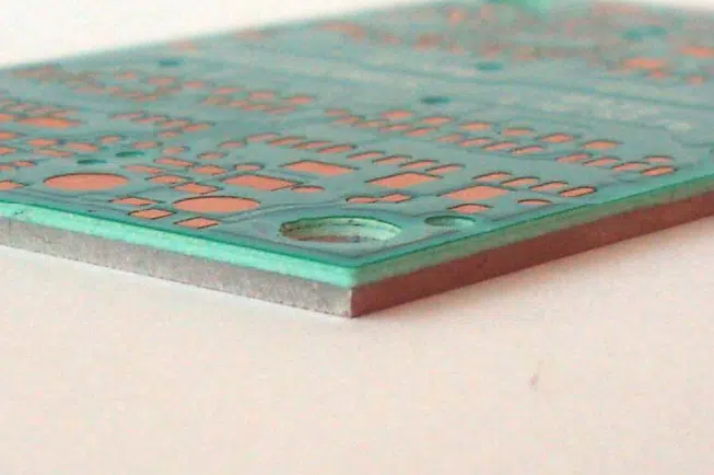
The type of material fabricating a printed circuit board determines its quality and performance. Some special situations demand PCBs to withstand large mechanical loads or extreme temperatures. Thus, some PCB boards must be made of materials that check all the right boxes. IMS (insulated Metal Substrate) PCBs are rescued in such a context. They solve some of the most pertinent concerns in PCB manufacturing, such as heat dissipation and component failure. Sounds fascinating? Join us as we explore the Z to Z of IMS PCBs.
What is an IMS PCB?
IMS PCB are a specialized set of printed circuit boards devised to enhance thermal management and reliability in electronic components. They comprise a metal core, typically aluminum or copper, facilitating efficient heat dissipation. Thus, they are ideal for high-power applications where thermal management is crucial, such as telecommunications systems, power converters, LED lighting, etc. An IMS PCB is integrated into a dielectric layer that ensures electrical insulation and a copper circuit layer for component placement.
IMS PCBs effectively dissipate heat away from sensitive components, enhancing performance, increasing component shelf-life, and bolstering the reliability of electronic devices. Their unique construction and useful characteristics empower engineers and designers to address heat-related challenges, enabling the production of compact, efficient, and dependable electronic systems for multiple industries.
What are the Benefits of Using IMS PCBs?
An IMS PCB has many advantages over normal FR4 boards. These include –
- Excellent Heat Dissipation
As we hinted at in the beginning, heat buildup is one of the biggest problems for PCB manufacturers. IMS-printed circuit boards emerge as the ideal solution, as they transfer heat to another layer of the circuit board without damaging the device. Moreover, the circuit’s metal core is equipped with heat-transferring vias that enable heat transfer from the top of the components to the substrate’s bottom side.
- Superb Thermal Conductivity
IMS PCB have amazing thermal conductivity, ranging from 1 – 12 W. Its metal core thickness varies between 0.4 mm to 3.2 mm. The dielectric polymer layers ensure low thermal resistivity and superior thermal conductivity. Thus, they are much better than other PCBs and can function from about 140 degrees C to 150 degrees C. Moreover, by leveraging the increased thermal components, high heat-dissipating components can be densely packed in IMS PCB, thereby increasing their overall compactness.
- Lower Weight and Better Recycling Potential
IMS boards are lighter than their counterparts and offer more conductivity than conventional printed circuit boards made from epoxy materials. Furthermore, IMS PCB are environmentally friendly, as metal is their core base layer material. Lastly, aluminum is easily recyclable and less expensive, making it easier to mine and refine.
- Amazing Electronic Properties
The fourth advantage of an IMS PCB is its unique electronic properties. IMS PCBs are less fire-prone than FR4 PCBs, making them a superb choice for high-power applications or applications where the environment temperature is high or flammable.
- Durability
Lastly, IMS PCB are more durable and much more robust than PCBs composed of epoxy materials. The base materials of IMS boards – aluminum and copper- are strong, which minimizes the risk of accidental breakage.
Applications of IMS Boards
IMS PCBs have varied uses. For example, they are integral to LEDs, automotive industries, power electronics, solid-state relays, and more.
- LED Technology – LED circuits are becoming more compact, energy-efficient, and power dense over time. Such LED circuits depend on IMS PCB because they can absorb heat generated from LEDG SMDs and efficiently transfer that heat to the heatsink material.
- Power Electronics – Power electronic circuits with switching devices generate excessive heat. Without any heatsink er components, IMS PCB efficiently disperse heat. Thus, the designs become more compact.
- Automotive Industry – IMS boards have pertinent usage in the automotive industry. Modern vehicles comprise dozens of control units (CU). Such small components are placed in or near the engine and are susceptible to high and scorching temperatures. IMS PCB provide the required thermal conductivity and mechanical properties suitable for these applications.
- Solid State Relays – Another veritable use of IMS boards is in Solid State Relays (SSR). To begin with, SSR is the modern equivalent of mechanical relays. They are made composed of a power switch and a driver circuit for an optocoupler (TRIAC or MOSFET). All components are packed into a small casing, which serves as the heat sink. They must resort to IMS PCB to encapsulate heat from all the components and forward that heat to the enclosure.
Different Types of IMS Boards
There are multiple types of IMS PCBs. These include
Single-sided IMS PCB
One-sided IMS PCB have trace prints. The board structure has a metal base of copper or aluminum, a copper circuit layer, a dielectric layer, and a non-conducting solder mask.
Double-sided IMS PCB
A double-sided IMS board ensures high functionality. Two sides comprise trace prints, and the base material is copper, aluminum, or alloy. Two component-populated solder mask layers make up a double-sided IMS PCB.
Multi-layer IMS PCB
The third type of IMS PBC has multiple layers, which means more functionality. Multi-layer IMS boards have more components, such as signal and ground layers. The application requirement determines the choice of metal for the base layer of the board. Furthermore, multi-layer IMS PCBs have the most complicated arrangements, featuring copper layers typically sandwiched at the bottom and top sides of the metal boards.
Types of IMS Boards Depending on PCB Layer and Position for Component Mounting
When considering the layer (PCB) and location for component mounting, we have four distinct IMS boards, namely:
- IMS Printed Circuit Boards with Dual Mounting Pads for Electronic Components – IMS PCBs with such a design have two solder mask layers. The exciting part is that each layer of solder mask can contain a unique set of features. In addition to the two mounting holes, IMS boards with dual mounting are distinguished by a metal substrate in the center of the board and vias – for transforming current and heat. In addition, there is resin material surrounding the vias and providing insulation. IMS PCBs with such a design render increased mechanical performance and average heat sink abilities. However, they can only create complex circuits.
- Single-sided Meta PCBs (Core IMS) – PCBs with such an IMS layout only require a single solder mask layer. They also feature a metal substrate and a single copper layer. These layouts shine in the case of elementary circuits, such as LEDs and SSRS. The bottom metal substrate also serves as a heatsink.
- Two Layers with Single Mounting Side Component IMS PCBs – IMS PCB with such a design has two copper layers with an FR4 layer in between. These designs enable you to integrate more complex circuits and minimize thermal conductivity. Although the mitigation in thermal conductivity is not up to the mark, the design co=opts heat transferring vias as compensation. These vias can reach the bottom of SMD components and transfer heat to the substrate at the bottom.
The key distinctions between IMS and FR4 Printed Circuit Boards
It is time to underline the distinctions between IMS and FR4 PCBs. It is worth noting that R4 PCBs and IMS PCBs can be distinguished from one another in a variety of ways, not limited to thermal conductivity and mechanical qualities–
- In FR4 PCBs, we can mount through-hole components on single-layer PCBs. On the other hand, IMS PCBs of one layer do not support through-hole components.
- IMS PCBs generally have higher and better thermal conductivity when compared to the same layer-type FR4 PCB.
- Solder masks for FR 4 PCBs can be either black or green, amber, whereas they are white for IMS PCBs.
- In the fabrication of IMS PCBs, the substrate material is cut into sections using saw blades that have been coated with diamonds. On the reverse side, common machining techniques can be used for FR4.
- Most IMS PCBs can only handle one layer of copper, while FR4 PCBs can handle dozens. Due to the difficulty involved in producing multilayer IMS PCBs, you will find that they are the exception rather than the rule.
- Lastly, FR4 PCBs do not have any thickness limit, as they can hold many layers. On the contrary, thinner IMS PCBs are not permitted, where anything over that threshold, their benefits are nullified.
Absolute PCB assembly – Reliable IMS PCB Manufacturer
Absolute PCB is your one-stop shop for all IMS PCB manufacturing needs. You can order the PCB boards mentioned above and enjoy our one-to-one engineering support, accessible design for manufacturing, and design for excellence.