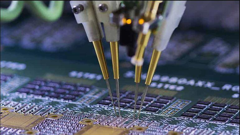
Important things You Should Know About In-Circuit Testing
Printed Circuit Boards or PCB’s are complicated as they are made up of several components and solder connections. Every component that needs to be used in the assembly of these boards needs to perform at its highest standards as a small defect can prove fatal for its performance and quality. In such a situation, it is necessary to test the separate components on the board along with its characteristics and this can be done with the help of in-circuit testing. Here in this article, you will learn more on this circuit board testing procedure and how it can help in diagnosing the fault in the components.
What is In-Circuit Testing?
In-circuit testing allows you to test all the defective components in the board individually and ensure that they are working fine. It gives highly accurate results and performs schematic verification. It is an automated test and helps in detecting the defects which can be replaced before the final designing is done. The circuit board testing method in this particular case is conducted in two parts which include power-off and power-on tests. The former tests are conducted right before they are supplied to the boards and the part is tested when the supply is on.
What kind of defects can be identified in In-Circuit Testing?
In-circuit tester method is hugely popular as it offers comprehensive test coverage compared to other testing techniques and helps in circuit board testing of each component on the board. Listed below are the following components which are tested using this print circuit board testing technique.
- Solder bridges
- Short circuits
- Component markings
- Soldering and process issues
- Lead spacing, component spacing, land and component sizes
- Shorts between component leads and traces
- Open circuits with electrical continuity
- Resistor values in the circuit
- Right location/setting of switches or jumpers
- Absence/presence of passive elements
- Absence/presence of active analog elements
- Analog components that are misoriented
- Digital elements that are misoriented
- Inductance and capacitance values
- Missing or wrong components
Although ICT is a great testing technique, it fails to detect the missing multiple power connections, mechanical fixings, decoupling capacitors, and sometimes the overall look of the board among other things as well.
Elements that are used In-Circuit Tester
You can find a wide variety of in-circuit test systems available in the market and each of these differ from each other in terms of its capabilities, testing procedures, and performance. Every PCB manufacturer should employ the right tester in order to access the required points on the circuitry. Moreover, here are the following components that you need to check when you are considering a PCB.
- Controller
- Software
- Analog Scanner
- Powered Analog Tests
- Analog Digital Opens
- Interface
- Fixture
ICT is a highly reliable technique which provides comprehensive testing and also ensures that the circuit is manufactured correctly to make it highly useful for the applications.
Advantages of In-Circuit Testing
ICT is fast, easy, and highly accurate in determining the fault in the circuits and is becoming hugely popular these days. This technique offers a wide variety of advantages which are as follows:
- It is easy to program while you are detecting defects in circuit components and ensure continuity and other related factors.
- It does not cause operator error.
- It usually takes around one or two minutes per assembly for testing the circuit and is highly economical for bulk processing.
- As it is a comprehensive testing method, it is highly reliable in comparison to the other testing methods.
- With this technique, you are assured of high fault coverage for handling the manufacturing defects.
- Interpreting the test results is extremely easy with this technique.
- It is ideal for through-hole conventional assemblies.
- It requires the least maintenance and its cost is also low.
Disadvantage of using ICT
ICT is highly comprehensive and accurate but it comes with its sets of disadvantages which are as follows:
- The test fixtures used in this technique are expensive.
- It is not easier to find connector faults in small package size SMT components that have high density with this testing.
- It is going to show inconsistency in results in case the test pins are not in proper contact with the right test pads.
- The test pins need to be cleaned frequently and replaced so as to avoid failure.
Even after the flaws, it is one of the best techniques that you will find in the industry for assembling the PCB’s.
It is extremely important to conduct proper inspection and testing on the PCB to ensure that the performance of every component meets the highest standards and enables them to finish the testing within a short span of time. This particular technique has been used for several years and is highly popular as it has the ability to produce responsive test requirements and all the major electronic firms use this technique to detect defects in the boards.

