Custom Shielding- The Best way to Create and Use It
Custom shielding is in trend and becoming a norm in the electrical and PCB manufacturing industry. This is because most devices nowadays come along with digital circuits that have semiconductor devices. Moreover, digital circuits also work at high frequencies.
One of the most often quoted statements we often stumble across regarding electronics is its harmful high frequencies emitted by the digital circuit boards. Custom shielding of the electronics is important as it mitigates the transfer of harmful frequencies.
What is custom shielding or circuit board shielding?
Circuit board shielding is the process of using the EMI shields, i.e., electromagnetic shields. They are useful in the following ways.
- They reduce the transmission of electromagnetic waves
- They avoid intrusion in sensitive electronic devices
These electromagnetic shields reduce the transmission of electromagnetic waves. Therefore, they inhibit the transfer of electromagnetic waves inside a device or from the device outwards. Custom shielding also uses the Radio Frequency Intrusion shields. They are useful in the following ways.
- They reduce the transmission of Radio frequency waves
- They avoid intrusion of radio frequency in electronic devices
The electronics and electrical devices manufactured nowadays emit more electromagnetic waves and radio frequency waves too.
These waves can be damaging to the human tissues due to long-term exposure to them, and they also can lead to the malfunction of the devices. Even the adjacent devices can suffer severe malfunction due to the continual exposure to the waves.
The device manufacturer has to make use of custom shielding to protect the users and the devices themselves from the harmful waves. Below are some of the fields widely using the custom shields.
- Medical devices
- Automotive components
- Aviation and aeronautical electronics
- Military devices
- Security devices
- Telecommunication equipment, namely smartphones
- Computer electronics

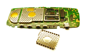
The above image shows the shields of a disassembled mobile phone
Considering the right material
Before finalising the custom shield, you have to consider the frequency within the operable limits. Too much shielding, therefore, can be a problem; the device may not function optimally.
Frequencies emitted from electrical devices range from a few hertz to 50 GHz. Choosing the right material for the shielding purpose is essential as it will impact the EMI or RFI shield. Different metals have different levels of density; choosing one with the right density also needs choosing one with the right thickness and so forth.
There are different forms of materials with the following properties.
- Ability to shield frequencies
Those manufacturers trying to create a shield against a frequency of up to 15 MHz use steel. Steel is a ferromagnetic material and has the best bulk effect—an effect occurring within the entire bulk of a semiconductor instead of a specific region.
- Solderability
Metals are the best options for making custom shields that block the radio frequencies and electromagnetic frequencies. However, not all metals have the best ability to bond. Choosing the right type of steel, therefore, also depends on the material’s solderability.
All types of steel have more or less the same ability to block the harmful waves, whereas pre-tin plated steel as a material offers excellent solderability.
- Weight
In the quest of choosing the right material that blocks the most of such harmful waves, choosing a very dense metal can add unnecessary bulk to the shield. The manufacturer has to opt for a sufficiently dense yet highly malleable metal or alloy. Steels, nickel silver, copper, and brass are some of the choicest metals and alloys.
Standard Base Materials used for Shielding
Out of the different metals used for shielding, the three most significant metals are used by engineers for making custom shields. They are as follows.
- Pre-tin plated steel
As stated above, steel can block harmful waves with frequencies of up to 15 MHz. Besides, steel is readily available and highly plastic; therefore, engineers can make structures with different thicknesses.
Steel is also very affordable for those who are budget-minded. Pre-tin plated steel is also resistant to rusting and is highly solderable.
- Aluminum
Aluminum is another choice material in making custom shields for electronic gadgets. It is 60% more conductive than copper is. It is malleable and plastic, too. The biggest advantage of aluminum is that it is significantly light yet very strong.
One of the biggest detractors of aluminum as a metal is it tends to corrode due to oxidation and galvanic corrosion.
- Copper alloy 770
Another commonly preferred alloy for manufacturing custom shields for electronics is the copper alloy 770. The alloy consists of three components, namely nickel, zinc, and copper. The copper alloy 770 is highly suitable for custom electromagnetic and radio frequency waves shielding. The perfect combination of three metals also makes the alloy resistant to corrosion.
Also read:- Aerospace PCB Assembly
Available Custom Board Shielding kinds:
In terms of structure and fitting, there are mainly three types of custom board shields. They are as follows with their subtypes.
- One-piece surface mount
The one-piece surface mount comes as a single piece attachment option. Fixing and unfixing it need operating just one attachment.
It comes in either a closed surface mount or a vented surface mount—the former suits covering the electrical components that do not need ventilation or connection to the external components. In comparison, the latter suits electrical components needing ventilation or connection to the external components.
- Two-piece surface mount shielding
The two-piece surface mount shielding comes as a double piece attachment option. Attaching and detaching this type of shielding need opening and closing two parts components.
This type of mount shielding comes in two options, namely low-profile slim shield and spring finger. They are elaborated as follows.
- Low profile slim shields: They come in two-piece broad level shielding lines, namely the cover piece and base piece. The cover piece locks into the dents at the base piece and is held securely there. The cover provides shield height as low as 0.06 inches. The photo-etching process provides freedom of wide-ranging designs. The affordable pricing is one of the most remarkable features. The hollowing tooling also gives various open locations that make this option a choice.
- Spring finger: This type of two-piece surface mount shielding is highly configurable. It has a unique spring finger design attachment between the cover and fence. It can be used for customizing configurations like L-shape, rectangular shape, V-shape, or any shape as desired. Also, brass and tin plating are the standard design components required, which are very easy to find.
3- CBS 2
This type of shielding has a six-sided custom shield. They come in standard forms with alloy 770; the shapes can be T, L, rectangle, and square. The shield also comes with cut-outs for input and output connectivity. They are highly effective in locking ventilation and closing all the holes.
PCB Methods
The most opted-for and recommended methods to block the harmful waves is to find the source of the frequency early. This enables the electronics and electrical engineers to resolve the problem before advancing with the designing process. Hence, here are 3 important steps that are necessary to sight the interference beforehand. They are as follows.
1- Use the smaller conductor trace in-between the power layer and the VCC pins’ PCB level. Then, scale back the common-mode interference. And then, you’ll be able to do that with 4-5 mil pre-peg inside the circuit layers.
Also, make sure to place all the power layers nearby the bottom layer. Now, the signal traces can be added to similar circuit layers.
2- The circuit layers need to be divided into high voltage segments such as:
- Switch mode supply
- Bridge Rectifiers
And you can divide the low segments into:
- Signal conditioner circuits
- Modulation circuits
- High-frequency amplification circuits
- Sensors
Later on, mix the filters of every unit nearer to each other.
3- Following issue with trying is to place traces remote from the edge of the PCB. Also, keep track of the PCB breadth. You must make sure that the PCB dimension is tiny to lower down its resistance.
Hence, use nearly a hundred thirty-five degrees corner trace. It’s best to confirm that the signal tracks are as small as possible. Moreover, digital GND and analog GND must be far away.
Advantages of Photo Etched Board Level Shielding
- It is an inexpensive option to craft tools
- It offers more design flexibility
- It allows engraving beautiful logos, designs, and symbols without costing much
- It allows the attachment of pin designs that are available in every configuration
- It makes use of the available slots and through holes for dissipation of heat without any additional expense
- It offers complex geometry without any additional cost of tools
- The internal dividers are available for multi-cavity usage
Final Words
In electronic devices found nowadays, using custom shielding is an indispensable option. They help in the blocking of electromagnetic and radio frequency waves effectively. They are available in several types, i.e., in terms of shape, size, fitting, and materials used for making them.

